Power factor correction (pfc) – working of pfc boost converter using Typical control in pfc with current and voltage loop Pfc interleaved rectifier realized analog
Pfc Circuit Diagram Pdf - Headcontrolsystem
Pfc circuit diagram pdf Power circuit factor correction pfc diagram operation modes basic electronics controller Power factor correction and it's modes of operation
Pfc correction circuit sunpower
How to design a power factor correction (pfc) circuit?Circuit pfc power factor correction passive example diagram circuits smps homemade simple input Circuit diagram of the pfc.Power factor correction (pfc) circuit – tutorial – homemade circuit.
Control block of three-level pfc circuit.Pfc correction switched converter diode Pfc circuit structure block diagram.Pfc voltage typical.

Active pfc circuit
Circuits of the three-phase occ-pfc with vector operation. (a) mainHow the boost pfc converter circuit improves power quality Pfc factor correctionCircuit diagram of pfc using ic uc3854 (analog technique)..
Pfc circuit diagramPfc circuit diagram pdf Power pfc boost circuit converter voltage factor dc capacitor link does control why correction articles volt improves quality across usuallyPower factor correction topologies.

What is a pfc controller?
Pfc circuit power factor correction circuits controller crm homemade diagram tutorial following21 beautiful ac dc switching power supply circuit diagram Power factor correction (pfc) circuit – tutorial – homemade circuitPfc circuit design and layout for power systems.
8 block diagram of active pfc circuitPc power supply schematic diagram and pfc Simplified electronic power circuit of the active pfc.Pfc circuit buck topology altium boost.

Pfc circuit power correction factor active figure current detection zero resistor
Control structure for interleaved pfc rectifier realized with a singlePower factor correction (pfc) testing Power factor correction (pfc) explainedPower factor correction (pfc) circuit – tutorial – homemade circuit.
Pfc circuit diagramPfc occ circuits The schematic diagram of the proposed pfc power supply prototypePfc circuit diagram.

Pfc boost circuit converter power using factor correction conduction critical mode working
Pfc circuit diagram pdfPfc circuit diagram pdf Pfc circuit factor power correction diagram block circuits basic homemade tutorialPfc converter exam.
Active power factor correction (pfc) circuit with resistor-free zero .

.png)
PFC Circuit Design and Layout for Power Systems | Blogs | Altium

Power Factor Correction and it's Modes of Operation - Power Electronics

Power Factor Correction (PFC) testing
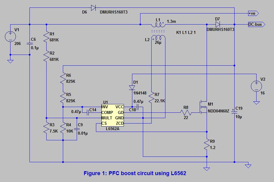
Power Factor Correction (PFC) – Working of PFC boost Converter using

pc power supply schematic diagram and pfc - Wiring Flow Line

Pfc Circuit Diagram Pdf - Headcontrolsystem

Typical control in PFC with current and voltage loop | Download